Friday 29 May 2015

Troubleshoot BGP Routes

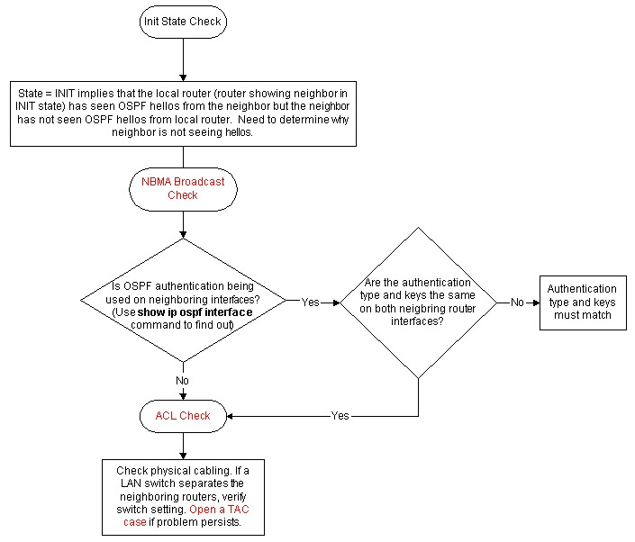
Routes Announced Using a Basic Network Statement

When routes are announced using a basic network statement, the behavior of the network command varies depending on whether auto-summary is enabled or disabled. When auto-summary is enabled, it summarizes the locally originated BGP networks (network x.x.x.x) to their classful boundaries (auto-summary is enabled by default in BGP). If a subnet exists in the routing table and these three conditions are satisfied, any subnet (component route) of that classful network in the local routing table prompts BGP to install the classful network into the BGP table:
  • Auto-summary enabled
  • Classful network statement for a network in the routing table
  • Classful mask on that network statement
When auto-summary is disabled, the routes introduced locally into the BGP table are not summarized to their classful boundaries.
For example, BGP introduces the classful network 75.0.0.0 mask 255.0.0.0 in the BGP table if these conditions are met:
  • The subnet in the routing table is 75.75.75.0 mask 255.255.255.0.
  • You configure network 75.0.0.0 under the router bgp command.
  • Auto-summary is enabled.
If these conditions are not all met, BGP does not install an entry in the BGP table unless there is an exact match in the IP routing table.

Troubleshooting Steps

With auto-summary enabled on R101, the router is not able to announce classful network 6.0.0.0/8 to R102.
bgp_noad_01.gif
  1. Check to see if R101 announces 6.0.0.0/8 to R102. The output shown confirms that R101 does not announce 6.0.0.0/8 to R102.
    R101# 
    show ip bgp neighbors 10.10.10.2 advertised-routes
    R101#
  2. Check the running configuration. The example shown illustrates that R101 is configured with classful network statement. Auto-summary is enabled by default in the Cisco IOS software version used for this scenario.
    R101#
    show running-config | begin bgp
    router bgp 1
    network 6.0.0.0
    neighbor 10.10.10.2 remote-as 2
    [...]
  3. Check to see if you have a component route (a classful route or a subnet route) of network 6.0.0.0/8 in the routing table.
    R101#
    show ip route 6.0.0.0 255.0.0.0 longer-prefixes
    R101#
  4. Because there is no component route (no classful route or subnet route ) in the R101 IP routing table, the network 6.0.0.0 in not installed in the BGP table. The minimum requirement for a prefix configured under the network command to be installed in a BGP table is to have a component route in the IP routing table. So make sure that R101 has a component route for network 6.0.0.0/8 either by learning it through IGP or through static configuration. In the example shown, the static route is configured to null 0.
    R101(config)# ip route 6.6.10.0 255.255.255.0 null 0 200
    
  5. As soon as the IP routing table has a component route for 6.0.0.0/8, BGP installs a classful network in the BGP table.
    R101# show ip route 6.0.0.0 255.0.0.0 longer-prefixes
    [..]
    6.0.0.0/24 is subnetted, 1 subnets
    S 6.6.10.0 is directly connected, Null0
  6. To bring the change into effect in BGP and start announcing network 6.0.0.0/8 to R102, you must either clear the BGP neighbor or do a soft reset to peer. This example shows a soft reset outbound to peer 10.10.10.2 to bring the changes into effect. For more details on soft reset, see the Managing Routing Policy Changes section in Configuring BGP.
    R101# clear ip bgp 10.10.10.2 [soft] out
    R101#
  7. To bring the change into effect in BGP and start announcing network 6.0.0.0/8 to R102, you must either clear the BGP neighbor or do a soft reset to peer. This example shows a soft reset outbound to peer 10.10.10.2 to bring the changes into effect. Refer to the Managing Routing Policy Changes section in Configuring BGP for more information on soft reset.
    R101# show ip bgp | include 6.0.0.0
    *> 6.0.0.0 0.0.0.0 0 32768 i
  8. The show ip bgp command confirms that classful network 6.0.0.0/8 is introduced into BGP.
    R101# show ip bgp | include 6.0.0.0
    *> 6.0.0.0 0.0.0.0 0 32768 i
  9. Confirm that R101 announces routes to R102.
    R101# show ip bgp neighbors 10.10.10.2 advertised-routes | include 6.0.0.0
    *> 6.0.0.0 0.0.0.0 0 32768 i
    Note: With auto-summary disabled, BGP installs network 6.0.0.0/8 only when there is a exact matching route in the routing table. If there are subnet routes but no exact matching route (6.0.0.0/8) in the routing table, then BGP does not install the network 6.0.0.0/8 in the BGP table.

Routes Announced Using the Network Statement with a Mask

Networks that fall on a major net boundary (255.0.0.0, 255.255.0.0, or 255.255.255.0) do not need to have a mask included. For example, the network 172.16.0.0 command is sufficient to send the prefix 172.16.0.0/16 into the BGP table. However, networks that do not fall on major net boundaries are required to have a network statement with a mask, such as network 172.16.10.0 mask 255.255.255.0.
An exact route in the routing table is required for a network statement with a mask in order for it to be installed into a BGP table.

Troubleshooting Steps

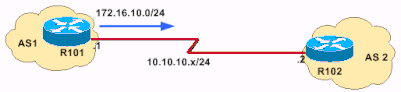
R101 is unable to announce network 172.16.10.0/24 to R102.
bgp_noad_02.gif
  1. Check to see if R101 announces the 172.16.10.0/24 prefix to R102.
    R101# show ip bgp neighbors 10.10.10.2 advertised-routes
    R101#
    OR
    This command can be used to check whether the routes are being advertised:
    R101#show ip bgp 172.16.10.0/24
    R101# BGP routing table entry for 172.16.10.0/24, version 24480684
    Bestpath Modifiers: deterministic-med
    Not advertised to any peer <---- not advertised to any peers
    Paths: (4 available, best #3)
    The output above confirms that R101 is not announcing 192.168.32.0/22 to R102.
  2. Check the running configuration.
    R101# show run | begin bgp
    router bgp 1
    network 172.16.10.0
    Note: You want to originate network 172.10.10.0/24. This network does not fall on the boundary of a Class B network (255.255.0.0). A network statement with mask 255.255.255.0 needs to be configured to make it work.
  3. After a network statement with mask is configured, the show run command shows output similar to this:
    R101# show run | begin bgp
    router bgp 1
    network 172.16.10.0 mask 255.255.255.0
  4. Check to see if the route is in the BGP routing table.
    R101# show ip bgp | include 172.16.10.0
    R101#
    Network 172.16.10.0/24 does not exist in the BGP table.
  5. Check to see if there is an exact route in the IP routing table. The output shown confirms that there is not an exact route in the routing table.
    R101# show ip route 172.16.10.0 255.255.255.0
    % Network not in table
    R101#
  6. Decide which routes you want to originate. Then either fix the IGP or configure static routes.
    R101(config)# ip route 172.16.10.0 255.255.255.0 null 0 200
    
  7. Check the IP routing table.
    R101# show ip route 172.16.10.0 255.255.255.0 longer-prefixes
    [..]
    172.16.0.0/24 is subnetted, 1 subnets
    S 172.16.10.0 is directly connected, Null0
  8. Verify that the routes are in the BGP table.
    R101# show ip bgp | include 172.16.10.0
    *> 172.16.10.0/24 0.0.0.0 0 32768 i
  9. To bring the change into effect in BGP and start announcing network 6.0.0.0/8 to R102, you must either clear the BGP neighbor or do a soft reset to the peer. This example uses a soft reset outbound to peer 10.10.10.2. For more details on soft resets, see the Managing Routing Policy Changes section in Configuring BGP.
    R101# clear ip bgp 10.10.10.2 [soft] out
    
  10. Confirm that routes are being advertised to R102.
    R101# show ip bgp neighbors 10.10.10.2 advertised-routes | include 172.16.10.0
    *> 172.16.10.0/24 0.0.0.0 0 32768 i

Routes Announced Using the aggregate-address Command

BGP allows the aggregation of specific routes into one route using the aggregate-address address mask command. Aggregation applies to routes that exist in the BGP routing table. This is in contrast to the network command, which applies to the routes that exists in IP routing table. Aggregation can be performed if at least one or more of the specific routes of the aggregate address exists in the BGP routing table. Refer to Understanding Route Aggregation in BGP for more information on BGP aggregation and associated attributes.

Troubleshooting Steps

bgp_noad_03.gif
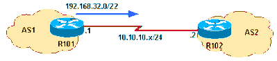
In this network diagram, R101 is unable to announce the aggregate address 192.168.32.0/22 to R102. Network 192.168.32.0/22 aggregates these three Class C address spaces:
  • 192.168.33.0/24
  • 192.168.35.0/24
  • 192.168.35.0/24
  1. Confirm that R101 is not announcing 192.168.32.0/22 to R102.
    R101# show ip bgp neighbors 10.10.10.2 advertised-routes | include 192.168.32.0
    R101#
  2. Check the running configuration.
    router bgp 1
    [..]
    aggregate-address 192.168.32.0 255.255.252.0 summary-only
    neighbor 10.10.10.2 remote-as 2
    R101 is configured to announce only the aggregate address to R102 using the "summary-only" attribute.
  3. Check the IP routing table.
    R101# show ip route 192.168.32.0 255.255.252.0 longer-prefixes
    [..]
    S 192.168.33.0/24 is directly connected, Null0
    The IP routing table has the component route of aggregate 192.168.32.0/22; however for an aggregate address to be announced to a peer, a component route must exist in the BGP routing table rather than in the IP routing table. The IP routing table has the component route of aggregate 192.168.32.0/22; however for an aggregate address to be announced to a peer, a component route must exist in the BGP routing table rather than in the IP routing table.
  4. Check to see if a component route exists in the BGP routing table.
    R101# show ip bgp 192.168.32.0 255.255.252.0 longer
    R101#
    The output confirms that the BGP table does not have a component route, so the next logical step is to ensure that a component route exists in the BGP table.
  5. In this example, a component route 192.168.33.0 is installed into the BGP table using the network command.
    R101(config)# router bgp 1
    R101(config-router)# network 192.168.33.0
  6. Check to see if the component route exists in the BGP table.
    R101# show ip bgp 192.168.32.0 255.255.252.0 longer-prefixes
    BGP table version is 8, local router ID is 10.10.20.1
    Status codes: s suppressed, d damped, h history, * valid, > best, i - internal
    Origin codes: i - IGP, e - EGP, ? - incomplete
    *> 192.168.32.0/22 0.0.0.0 32768 i
    Network Next Hop Metric LocPrf Weight Path
    R101#
    s> 192.168.33.0 0.0.0.0 0 32768 i
    The "s" means that the component route is suppressed due to the "summary-only" argument.
  7. Confirm that the aggregate is announced to R102.
    R101# show ip bgp n 10.10.10.2 advertised-routes | include 192.168.32.0/22
    *> 192.168.32.0/22 0.0.0.0

Unable to Announce iBGP-Learned Routes

A BGP router with synchronization enabled will not advertise iBGP-learned routes to other eBGP peers if it is not able to validate those routes in its IGP. Assuming that IGP has a route to iBGP-learned routes, the router will announce the iBGP routes to eBGP peers. Otherwise the router treats the route as not being synchronized with IGP and does not advertise it. Disabling synchronization using the no synchronization command under router BGP prevents BGP from validating iBGP routes in IGP. Refer to the Synchronization section of BGP Case Studies for more information.

Troubleshooting Steps

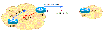
In the diagram shown, R101 learns prefix 130.130.130.0/24 from R103 through iBGP and is unable to announce it to eBGP peer R102.
bgp_noad_04.gif
  1. First check R101.
    R101# show ip bgp neighbors 10.10.20.2 advertised-routes | include 130.130.130.0
    R101#
    The above output confirms that R101 is not announcing prefix 130.130.130.0/24 to R102. Look at the BGP table on R101:
    R101# show ip bgp 130.130.130 255.255.255.0 longer
    BGP table version is 4, local router ID is 10.10.20.1
    Status codes: s suppressed, d damped, h history, * valid, > best, i - internal
    Origin codes: i - IGP, e - EGP, ? - incomplete
    * i130.130.130.0/24 10.10.20.3 0 100 0 i
    Network Next Hop Metric LocPrf Weight Path R101#
    Network 130.130.130.0/24 exists in the BGP table. However the network 130.130.130.0/24 does not have the status code of best route (>). This means that the BGP Best Path Selection Algorithm did not choose this prefix as the best path. Since only the best paths are announced to BGP peers, network 130.130.130.0/24 is not announced to R102. Next, you need to troubleshoot why the BGP path selection criteria did not select this network as the best route.
  2. Examine the output of the show ip bgp prefix command to give you more details on why the prefix was not chosen as the best route nor installed in IP routing table.
    R101# show ip bgp 130.130.130.0
    BGP routing table entry for 130.130.130.0/24, version 4
    Paths: (1 available, no best path)
    10.10.20.3 from 10.10.20.3 (130.130.130.3)
    Not advertised to any peer Local
    Origin IGP, metric 0, localpref 100, valid, internal, not synchronized
    The output shows that prefix 130.130.130.0/24 is not synchronized.
    Note: Before the identification of bug CSCdr90728 ("BGP paths are not marked as not synchronized"), the show ip bgpprefix command did not show the paths marked as not synchronized. This problem is corrected in Cisco IOS Software Releases 12.1(4) and later.
  3. Check the running BGP configuration.
    R101# show ip protocols
    Routing Protocol is "bgp 1"
    Outgoing update filter list for all interfaces is not set
    Incoming update filter list for all interfaces is not set
    IGP synchronization is enabled
    Automatic route summarization is disabled
    Neighbor(s):
    Address FiltIn FiltOut DistIn DistOut Weight RouteMap
    10.10.10.2
    Routing for Networks:
    10.10.20.3 Maximum path: 1 Routing Information Sources:
    Distance: external 20 internal 200 local 200
    Gateway Distance Last Update
    10.10.20.3 200 01:48:24
    The above output shows that BGP synchronization is enabled. BGP synchronization is enabled by default in Cisco IOS software.
  4. Configure BGP to disable synchronization. Issue the no synchronization command under router BGP.
    R101(config)# router bgp 1
    R101(config-router)# no synchronization
    R101# show ip protocols
    Routing Protocol is "bgp 1"
    Outgoing update filter list for all interfaces is not set
    Incoming update filter list for all interfaces is not set
    IGP synchronization is disabled
    Automatic route summarization is disabled
    Neighbor(s):
    Address FiltIn FiltOut DistIn DistOut Weight RouteMap
    10.10.10.2
    Routing for Networks:
    10.10.20.3 Maximum path: 1 Routing Information Sources:
    Distance: external 20 internal 200 local 200
    Gateway Distance Last Update
    10.10.20.3 200 01:49:24
    During the next run of the BGP scanner, which scans the BGP table every 60 seconds and makes decision based on BGP path selection criteria, network 130.130.130.0 will be installed (since the synchronization is disabled). This means that the maximum time for the route to be installed is 60 seconds, but it may be less, depending on when the no synchronizationcommand is configured and when the next instance of the BGP scanner occurs. So it is best to wait for 60 seconds before the next step of verification.
  5. Verify that the route has been installed.
    The output shown confirms that prefix 130.130.130.0/24 is the best route; therefore, it is installed into the IP routing table and is propagated to peer 10.10.10.2.
    R101# show ip bgp 130.130.130.0
    BGP routing table entry for 130.130.130.0/24, version 5
    Paths: (1 available, best #1, table Default-IP-Routing-Table)
    Advertised to non peer-group peers:
    10.10.10.2
    Local
    10.10.20.3 from 10.10.20.3 (130.130.130.3)
    Origin IGP, metric 0, localpref 100, valid, internal, best
    R101# show ip bgp neighbors 10.10.10.2 advertised-routes | include 130.130.130.0/24
    *>i130.130.130.0/24 10.10.20.3 0 100 0 i

Routes Announced with Redistribute Static

If the routers are connected with two links, and the routes are learned through BGP and floating static routes, the floating static routes are installed in the routing table. This occurs if the static routes are redistributed in the case of BGP route failure. If the BGP routes come back online, the floating static routes in the routing table are not changed to reflect the BGP routes.
This issue can be solved if you remove the redistribute static command under the BGP process to avoid the prioritization of floating static routes over BGP routes.

Thursday 28 May 2015

Troubleshoot Duplicate Route ID

Troubleshooting

The troubleshooting was done with a Cisco IOS software release released before the Cisco bug ID CSCdr61598 (registered customers only) and Cisco bug ID CSCdu08678 (registered customers only) integration.

Single Area Network

This image is a representation of the single area network described in these steps.
duplicate_router_id_ospf1.gif
  1. Issue the show proc cpu | include OSPF command. This allows you to see the OSPF processes that utilize the CPU.
    r4#show proc cpu | include OSPF
    3 4704 473 9945 1.38% 0.81% 0.68% 0 OSPF Hello
    71 9956 1012 9837 1.47% 1.62% 1.41% 0 OSPF Router
    As seen in the previous example, there is high CPU for OSPF. This shows that there must be something wrong with either the link stability or a duplicate router-id.
  2. Issue the show ip ospf statistics command. This allows you to see if the SPF algorithm is run more than ordinary.
    r4#show ip ospf statistics
    Area 0: SPF algorithm executed 46 times
    SPF calculation time
    Delta T Intra D-Intra Summ D-Summ Ext D-Ext Total Reason
    00:01:36 0 0 0 0 0 0 0 N,
    00:01:16 0 0 0 0 0 0 0 R, N,
    00:01:26 0 0 0 0 0 0 0 R, N,
    00:00:56 0 0 0 0 0 0 0 R, N,
    00:01:06 0 0 0 0 0 0 0 R, N, 00:00:46 0 0 0 0 0 0 0 R, N,
    00:00:26 0 0 0 0 0 0 0 R, N,
    00:00:36 0 0 0 0 0 0 0 R, N, kmbgvc 00:00:16 0 0 0 0 0 0 0 R, N,
    00:00:06 0 0 0 0 0 0 0 R, N,
    The show ip ospf statistics command shows that recalculation of SPF is done every 10 seconds, as seen in the previous example. It is triggered by the router and network LSA. There is a problem in the same area as the current router.
  3. Issue the show ip ospf database command.
    r4#show ip ospf database
    OSPF Router with ID (50.0.0.4) (Process ID 1)
    Router Link States (Area 0)
    Link ID ADV Router Age Seq# Checksum Link count
    50.0.0.1 50.0.0.1 681 0x80000002 0x7E9D 3
    50.0.0.4 50.0.0.4 705 0x80000003 0x83D 4
    50.0.0.2 50.0.0.2 674 0x80000004 0x2414 5 50.0.0.5 50.0.0.5 706 0x80000003 0x5C24 6
    50.0.0.6 50.0.0.6 16 0x80000095 0xAF63 6 50.0.0.7 50.0.0.7 577 0x80000005 0x86D5 8 Net Link States (Area 0)
    192.168.2.6 50.0.0.6 6 0x8000007A 0xABC7
    Link ID ADV Router Age Seq# Checksum
    The show ip ospf database command shows that one LSA is newer (age 16) and its sequence number is much higher then the other LSAs in the same OSPF database. You need to figure out which router sent this LSA. Since it is in the same area, the advertising router id is known (50.0.0.6). It is more probable that this router ID is duplicated. You need to find out which other router has the same router-id.
  4. This example shows several instances of the show ip ospf database command.
    r4#show ip ospf database router adv-router 50.0.0.6
    OSPF Router with ID (50.0.0.4) (Process ID 1)
    Router Link States (Area 0) LS age: 11
    Link State ID: 50.0.0.6
    Options: (No TOS-capability, DC) LS Type: Router Links Advertising Router: 50.0.0.6
    Link connected to: a Transit Network
    LS Seq Number: 800000C0 Checksum: 0x6498 Length: 72 Number of Links: 4
    Number of TOS metrics: 0
    (Link ID) Designated Router address: 192.168.2.6 (Link Data) Router Interface address: 192.168.2.6 TOS 0 Metrics: 10
    (Link ID) Neighboring Router ID: 50.0.0.7
    Link connected to: another Router (point-to-point)
    (Link Data) Router Interface address: 192.168.0.21
    Number of TOS metrics: 0 TOS 0 Metrics: 64
    (Link ID) Network/subnet number: 192.168.0.20
    Link connected to: a Stub Network (Link Data) Network Mask: 255.255.255.252
    Link connected to: a Stub Network
    Number of TOS metrics: 0 TOS 0 Metrics: 64 (Link ID) Network/subnet number: 50.0.0.6
    r4#show ip ospf database router adv-router 50.0.0.6
    (Link Data) Network Mask: 255.255.255.255 Number of TOS metrics: 0 TOS 0 Metrics: 1
    OSPF Router with ID (50.0.0.4) (Process ID 1)
    Router Link States (Area 0) LS age: 7
    Link State ID: 50.0.0.6
    Options: (No TOS-capability, DC) LS Type: Router Links Advertising Router: 50.0.0.6
    LS Seq Number: 800000C7
    !--- The sequence number has increased.
    Checksum: 0x4B95
    Length: 96
    Number of Links: 6
    !--- The number of links has increased although the network has been stable.
    Link connected to: a Stub Network
    (Link ID) Network/subnet number: 192.168.3.0
    (Link Data) Network Mask: 255.255.255.0
    TOS 0 Metrics: 10
    Number of TOS metrics: 0
    (Link ID) Neighboring Router ID: 50.0.0.5
    Link connected to: another Router (point-to-point)
    TOS 0 Metrics: 64
    (Link Data) Router Interface address: 192.168.0.9 Number of TOS metrics: 0
    (Link Data) Network Mask: 255.255.255.252
    Link connected to: a Stub Network (Link ID) Network/subnet number: 192.168.0.8 Number of TOS metrics: 0
    (Link ID) Neighboring Router ID: 50.0.0.2
    TOS 0 Metrics: 64 Link connected to: another Router (point-to-point) (Link Data) Router Interface address: 192.168.0.2
    (Link ID) Network/subnet number: 192.168.0.0
    Number of TOS metrics: 0 TOS 0 Metrics: 64 Link connected to: a Stub Network (Link Data) Network Mask: 255.255.255.252
    (Link Data) Network Mask: 255.255.255.255
    Number of TOS metrics: 0 TOS 0 Metrics: 64 Link connected to: a Stub Network (Link ID) Network/subnet number: 50.0.0.6 Number of TOS metrics: 0
    TOS 0 Metrics: 1
  5. If you know your network, you can find which router advertises those links. The first previous output shows that the LSAs are sent by a router with OSPF neighbors 50.0.0.7, whereas the second output shows neighbors 50.0.0.5 and 50.0.0.6. Issue the show ip ospf command in order to find those routers and access them in order to verify their OSPF router-id. In this example setup, they are R6 and R3.
    3>show ip ospf
    Routing Process "ospf 1" with ID 50.0.0.6
    Supports only single TOS(TOS0) routes
    r6#show ip ospf
    Supports opaque LSA
    Routing Process "ospf 1" with ID 50.0.0.6
    Supports opaque LSA
    Supports only single TOS(TOS0) routes
  6. Issue the show run | beg router ospf command in order to check the configuration that starts at the OSPF configuration.
    R6#show run | include router ospf
    router ospf 1
    router-id 50.0.0.6
    log-adjacency-changes
    network 50.0.0.0 0.0.0.255 area 0
    network 192.168.0.0 0.0.0.255 area 0
    network 192.168.2.0 0.0.0.255 area 0
    r3#show run | begin router ospf
    router ospf 1
    log-adjacency-changes
    network 50.0.0.0 0.0.0.255 area 0
    network 192.168.0.0 0.0.0.255 area 0
    network 192.168.3.0 0.0.0.255 area 0
    In the previous example, the router-id command was removed and the OSPF process was not restarted. The same problem can also result from a loopback interface that is removed and configured somewhere else.
  7. Issue the clear ip ospf 1 process command and the show ip ospf command in order to clear the process.
    r3#clear ip ospf 1 process
    Reset OSPF process? [no]: y
    r3#show ip ospf
    Routing Process "ospf 1" with ID 50.0.0.6
    Supports only single TOS(TOS0) routes
    Supports opaque LSA
    As shown in the previous example, the wrong IP address still appears.
  8. Issue the show ip int brie command in order to check the interface.
    r3#show ip int brie
    Interface IP-Address OK? Method Status Protocol
    Ethernet0/0 192.168.3.1 YES NVRAM up up
    Serial2/0 192.168.0.9 YES NVRAM up up
    Serial1/0 192.168.0.2 YES NVRAM up up Loopback0 unassigned YES NVRAM up up
    Loopback1 50.0.0.6 YES NVRAM up up
    !--- The highest Loopback IP address
    In order to correct the problem, make sure that either the highest loopback configured on the router is unique in your OSPF network, or configure statically the router-id with the router-id <ip address> command under the OSPF router configuration mode.

Multiple Areas with ASBR

The symptoms of these problems are that the external route, which is learned through the redistribution from static into OSPF process by R6, ASBR router flaps from the routing table on all routers within OSPF Area 0. The external route is 120.0.0.0/16 and the problem is noticed on Router 5 in Area 0. Start to troubleshoot from there.
duplicate_router_id_ospf2.gif
  1. Issue the show ip route command a few times consecutively in order to see the symptom.
    r5#show ip route 120.0.0.0
    Routing entry for 120.0.0.0/16, 1 known subnets
    O E2 120.0.0.0 [110/20] via 192.168.0.9, 00:00:03, Serial2/0
    r5#show ip route 120.0.0.0
    % Network not in table
    r5#
  2. Take a look at the OSPF database in order to check whether the LSA is received. If you issue the show ip ospf databasecommand several times in a row, you notice that the LSA is received by two routers, 50.0.0.6 and 50.0.0.7. If you look at the age of the second entry, if present, you notice that its value changes dramatically.
    r5#show ip ospf database | begin Type-5
    Type-5 AS External Link States
    Link ID ADV Router Age Seq# Checksum Tag
    120.0.0.0 50.0.0.6 2598 0x80000001 0xE10E 0
    r5#show ip ospf database | begin Type-5
    120.0.0.0 50.0.0.7 13 0x80000105 0xD019 0
    Type-5 AS External Link States
    Link ID ADV Router Age Seq# Checksum Tag
    120.0.0.0 50.0.0.6 2599 0x80000001 0xE10E 0
    120.0.0.0 50.0.0.7 14 0x80000105 0xD019 0
    r5#show ip ospf database | begin Type-5
    Type-5 AS External Link States
    Link ID ADV Router Age Seq# Checksum Tag
    120.0.0.0 50.0.0.6 2600 0x80000001 0xE10E 0
    r5#show ip ospf database | begin Type-5
    120.0.0.0 50.0.0.7 3601 0x80000106 0x6F6 0
    Type-5 AS External Link States
    Link ID ADV Router Age Seq# Checksum Tag
    120.0.0.0 50.0.0.6 2602 0x80000001 0xE10E 0
    r5#show ip ospf database | begin Type-5
    Type-5 AS External Link States
    Link ID ADV Router Age Seq# Checksum Tag
    120.0.0.0 50.0.0.6 2603 0x80000001 0xE10E 0
    r5#
  3. You also notice strange behavior if you look at the sequence number for the LSAs that are received from 50.0.07, which is the advertising router. Review what other LSAs are received from 50.0.0.7. If you issue the show ip ospf database adv-router 50.0.0.7 command several times in a row, the entries vary quickly, as shown in this example.
    r5#show ip ospf database adv-router 50.0.0.7
    OSPF Router with ID (50.0.0.5) (Process ID 1)
    Router Link States (Area 0)
    Link ID ADV Router Age Seq# Checksum Link count
    50.0.0.7 50.0.0.7 307 0x8000000D 0xDF45 6 Type-5 AS External Link States
    120.0.0.0 50.0.0.7 9 0x8000011B 0xA42F 0
    Link ID ADV Router Age Seq# Checksum Tag
    r5#show ip ospf database network adv-router 50.0.0.7
    OSPF Router with ID (50.0.0.5) (Process ID 1)
    r5#show ip ospf database network adv-router 50.0.0.7
    OSPF Router with ID (50.0.0.5) (Process ID 1)
    This last output does not show anything. Either the route is flapping or there is a problem of another kind, most probably a duplicate router ID within the OSPF domain.
  4. Issue the show ip ospf database command in order to view the external LSAs advertised by 50.0.0.7.
    r5#show ip ospf database external adv-router 50.0.0.7
    OSPF Router with ID (50.0.0.5) (Process ID 1)
    Type-5 AS External Link States
    Options: (No TOS-capability, DC)
    Delete flag is set for this LSA LS age: MAXAGE(3600)
    Advertising Router: 50.0.0.7
    LS Type: AS External Link Link State ID: 120.0.0.0 (External Network Number )
    Metric Type: 2 (Larger than any link state path)
    LS Seq Number: 80000136 Checksum: 0xA527 Length: 36 Network Mask: /16 TOS: 0
    r5#show ip ospf database external adv-router 50.0.0.7
    Metric: 16777215 Forward Address: 0.0.0.0 External Route Tag: 0
    OSPF Router with ID (50.0.0.5) (Process ID 1)
    r5#
  5. Look at the SPF calculation reasons in order to verify this. X means that SPF runs every 10 seconds because of an External LSA (type 5) flap and indeed, you see that SPF runs.
    r5#show ip ospf statistic
    Area 0: SPF algorithm executed 2 times
    SPF calculation time
    Delta T Intra D-Intra Summ D-Summ Ext D-Ext Total Reason
    00:47:23 0 0 0 0 0 0 0 X
    00:33:21 0 0 0 0 0 0 0 X
    00:46:33 0 0 0 0 0 0 0 X 00:32:05 0 0 0 0 0 0 0 X
    00:10:03 0 0 0 0 0 0 0 R, SN, X
    00:10:13 0 0 0 0 0 0 0 R, SN, X 00:09:53 0 0 0 0 0 0 0 R,
    00:09:23 0 0 0 0 0 0 0 X
    00:09:43 0 0 0 0 0 0 0 R, SN, X
    00:09:33 0 0 0 0 0 0 0 X
  6. It is known that the problem is outside the current area. Turn your focus on the ABR. Telnet to the ABR Router 2 in order to have more visibility on other areas than OSPF area 0. Issue the show ip ospf border-routers and show ip ospf database network adv-router commands.
    r2#show ip ospf border-routers
    OSPF Process 1 internal Routing Table
    Codes: i - Intra-area route, I - Inter-area route
    i 50.0.0.7 [20] via 192.168.2.1, Ethernet0/0, ASBR, Area 1, SPF 25
    r2#show ip ospf database network adv-router 50.0.0.7
    OSPF Router with ID (50.0.0.2) (Process ID 1)
    Net Link States (Area 1)
    Options: (No TOS-capability, DC)
    Routing Bit Set on this LSA LS age: 701 LS Type: Network Links
    Advertising Router: 50.0.0.7
    Link State ID: 192.168.1.2 (address of Designated Router) LS Seq Number: 80000001 Checksum: 0xBC6B Length: 32
    Attached Router: 50.0.0.1
    Network Mask: /24
    Attached Router: 50.0.0.7
  7. The faulty router is on the same LAN as 50.0.0.1. It must be Router 6. Issue the show ip ospf command.
    r6#show ip ospf
    Routing Process "ospf 1" with ID 50.0.0.7
    Supports only single TOS(TOS0) routes
    It is an autonomous system boundary router.
    Supports opaque LSA
  8. Once the faulty router is found, refer to the Single Area Network section of this document to correct the problem.

Error Message: %OSPF-4-FLOOD_WAR: Process 60500 flushes LSA ID 10.x.x.0 type-5 adv-rtr 10.40.x.x in area 10.40.0.0

The %OSPF-4-FLOOD_WAR: Process 60500 flushes LSA ID 10.35.70.4 type-5 adv-rtr 10.40.0.105 in area 10.40.0.0error message is received.
This error message states that the router originates or flushes LSA at a high rate. A typical scenario in a network may be where one router in the network originates LSA and the second router flushes that LSA. A detailed description of this error message is provided here:
  • Process 60500 - The OSPF process that reports the error. In this example, the process ID is 60500.
  • re-originates or flushes (keyword) - Indicates if the router originates LSA or flushes. In this error message, the routerflushes LSA.
  • LSA ID 10.35.70.4 - Link state ID for which a flood war is detected. In this example, it is 10.35.70.4.
  • type -5 - LSA type. This example has a Type 5 LSA.
    Note: A flood war has a different root cause for every LSA.
  • adv-rtr - Router which originates LSA (that is, 10.40.0.105).
  • Area - Area to which the LSA belongs. In this example, the LSA belongs to 10.40.0.0.

Tuesday 26 May 2015

Troubleshoot OSPF

Troubleshoot OSPF Neighbor States

Refer to OSPF Neighbor States for neighbor state descriptions.
ospf-neig-stat.jpg

Troubleshoot the OSPF Routing Table

ospf-rte-chk.jpg

Troubleshoot OSPF Init State

Refer to Why Does the show ip ospf neighbor Command Reveal Neighbors in the Init State? for an Init State problem description and troubleshooting steps.
init-state.jpg

Troubleshoot OSPF MTU

mtu-check.jpg
Note: If the problem is related to Layer 2, check if a proxy ARP is enabled. If it is enabled, disable it, and use the clear ip arpcommand in order to clear the ARP cache.

Troubleshoot OSPF Corrupt Packets

corrupt-packet.jpg

Troubleshoot OSPF Two-Way State

Refer to Why Does the show ip ospf neighbor Command Reveal Neighbors Stuck in 2-Way State? for an OSPF Two-way State problem description and troubleshooting steps.
two-way-chk.jpg

Troubleshoot OSPF Links

link-chk.jpg
You can use an Embedded Event Manager (EEM) script to troubleshoot the links flapping.
For more information, refer to this Cisco Support Community document that describes how to use an EEM script in order to collect information from a router when there is an OSPF flap: Troubleshooting OSPF Flaps with EEM Script leavingcisco.com

Troubleshoot Full Adjacency

full-adj-chk.jpg

Monday 25 May 2015

Troubleshoot EIGRP

Main Troubleshooting Flowchart

In order to troubleshoot EIGRP, use this flowchart, starting at the box marked Main. Depending on the symptoms, the flowchart might refer to one of the three flowcharts later in this document or to other relevant documents on Cisco.com. There are some problems that might not be resolvable here. In these cases, links are provided to Cisco Technical Support. In order to open a service request, you must have a valid service contract.
trouble_eigrp_01.gif

Neighbor Check

trouble_eigrp_02a.gif
Note: If you are not able to ping successfuly between neighbors, run the debug ip packet command in order to verify if the hellos are sent to Multicast Address 224.0.0.10.
Note: For example:
R1#debug ip packet
IP packet debugging is on
R1#
*Mar 1 00:10:54.643: IP: s=10.10.10.1 (local), d=224.0.0.10 (FastEthernet0/0), len 60, sending broad/multicast
R1#
*Mar 1 00:10:58.611: IP: s=10.10.10.2 (FastEthernet0/0), d=224.0.0.10, len 60, rcvd 2
!--- Indicates that the hello packets are sent to 224.0.0.10.
Flowchart Notes
1Issue the show ip eigrp interface command to verify.
2Issue the show interface serial command to verify.
trouble_eigrp_02b.gif
Note: If you experience the problems with EIGRP flapping across the GRE interface tunnel, it is possible that you have to configure thekeepalive 10 3 and ip tcp adjust-mss 1400 commands at both ends of the GRE tunnel. .
Flowchart Notes
3Issue the show ip interface command to verify.

Redistribution Check

trouble_eigrp_03.gif
Flowchart Notes
4Issue the show ip eigrp topology net mask command to verify.

Route Check

trouble_eigrp_04a.gif
Flowchart Notes
5Issue the show ip route eigrp command to verify.
6Issue the show ip eigrp topology command to verify. If routes are not seen in the topology table, issue the clear ip eigrp topology command.
trouble_eigrp_04b.gif
Flowchart Notes
7Issue the show ip eigrp topology net mask command, to find the Router ID (RID). You can find the local RID with the same command on the locally generated external router. In Cisco IOS Software Release 12.1 and later, the show ip eigrp topology command shows the RID.

Reasons for Neighbor Flapping

The stability of the neighbor relationship is of primary concern. A failure in the neighbor relationship is accompanied by increased CPU and bandwidth utilization. EIGRP neighbors can flap for these reasons:
  • Underlying link flaps. When an interface goes down, EIGRP takes down the neighbors that are reachable through that interface and flushes all routes learned through that neighbor.
  • Misconfigured hello and hold intervals. The EIGRP hold interval can be set independently of the hello interval if you issue the ip hold-time eigrp command. If you set a hold interval smaller than the hello interval, it results in the neighbors flapping continuously. Cisco recommends that the hold time be at least three times the hello interval. If the value is set less than 3 times the hello interval, there is the chance for link flapping or neighborship flapping.
    R1(config-if)#ip hello-interval eigrp 1 30
    R1(config-if)#ip hold-time eigrp 1 90
  • Loss of hello packets: Hello packets can be lost on overly congested links or error-prone links (CRC errors, Frame errors, or excessive collisions).
  • Existence of unidirectional links. A router on a unidirectional link can be able to receive hello packets, but the hello packets sent out are not received at the other end. The existence of this state is usually indicated by the retry limit exceeded messages on one end. If the routers generating retry limit exceeded messages has to form neighborship, then make the link bidirectional for both unicast and multicast. In case tunnel interfaces are used in the topology make sure that the interfaces are advertised properly.
  • Route goes stuck-in-active. When a router enters the stuck-in-active state, the neighbors from which the reply was expected are reinitialized, and the router goes active on all routes learned from those neighbors.
  • Provision of insufficient bandwidth for the EIGRP process. When sufficient bandwidth is not available, packets can be lost, which causes neighbors to go down.
  • Bad serial lines.
  • Improperly set bandwidth statements.
  • One-way multicast traffic.
  • Stuck in active routes.
  • Query storms.

EIGRP Neighbors are not Recognized

The EIGRP neighbor relationship is not established over the multipoint GRE tunnel if there is an incorrect NHRP association in the spoke. Next Hop Resolution Protocol (NHRP) is used to discover the addresses of other routers and networks behind the routers that are connected to a nonbroadcast multiaccess (NBMA) network. When a network statement under Eigrp covers both the physical interface and tunnel interface (tunnel interface ip address and physical interface ip address belong to the same major class) and if the phyiscal interface is the source of the tunnel, then the both interfaces have to be separately advertised in the Eigrp to avoid issues with DMVPN. The best practice is to advertise the interfaces using specific subnet advertisements.

This issue can be resolved when you clear the NHRP associations with this command: